STEP CUTER
STEP 1: Cut the outer jacket of the wire about 1.5" to 2" from the end. This will give you room to work with the wire pairs. Separate the pairs and align them in the order shown below. Begin flattening the wires into a "ribbon" as shown so that it will easily slip into the connector and into the individual channeled areas.
 ©CP3, Inc.
 STEP 2: Once you have all the wires aligned and ready to insert, you must trim them to approximately 1/2" in order to have as little "untwisted" wire in the connection as possible. Category 5 specifications require a certain number of twists per inch and even the connector counts!
 ©CP3, Inc.
 STEP 3: Insert the wires into the connector making sure that each wire goes into its appropriate "channel" and extends all the way to the end of the the connector underneath the gold crimping connectors. Sometimes you can look at the end of the connector to see the copper wires if you're using solid copper cable. If the wires don't extend to the end of the connector, the crimp may not make contact.
 ©CP3, Inc.
 STEP 4: Press the cable and the jacket into the connector firmly so that the jacket will be crimped by the plastic wedge near the rear of the connector, and insert it into your crimping tool and crimp the cable. RE-CRIMP the cable to make sure all connections are made.
STEP 5: Repeat steps 1 thru 4 for the other end of the cable for a standard ethernet cable.


CROSS CABLE
10-Base-T Crossover Cable
The following figure shows the correct wiring for a 10Base-T crossover cable (assuming you're using RJ-45 connectors).
This cable can be used to connect two computers together without a hub, or to connect two hubs together (without using an uplink port). If you're connecting two hubs together and one of them has an uplink port, use a straight cable (rather than the crossover) to connect the uplink port of one hub to one of the (non-uplink) ports of the other hub.
A bit of technical background: Most computer and workstation network adapter cards have interface ports referred to as MDI ports (RJ-45 pin assignments shown on the left side of the above drawing). "Uplink" ports on hubs have the same pin assignments. Most normal ports on hubs have MDI-X ports, which use pins 1 and 2 for receive, and pins 3 and 6 for transmit. A straight cable (one that connects pin 1 to pin 1, pin 2 to pin 2, etc.) can be used to connect an MDI port (a computer) to and MDI-X port (a normal port on a hub). Obviously, to connect two MDI ports together, it is necessary to connect pin 1 to pin 3, pin 2 to pin 6, and so forth.
RG 45
RJ-45
The RJ-45 connector is commonly used for network cabling and for telephony applications. It's also used for serial connections in special cases. Here's a look at it:
![]()
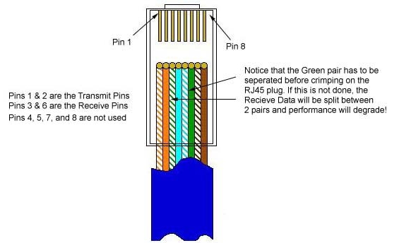
Also, please note that it is very important that a single pair be used for pins 3 and 6. If one conductor from one pair is used for pin 3 and a conductor from another pair is used for pin 6, performance will degrade. See the following figure.
To learn more about Ethernet, check out Charles Spurgeon's Ethernet Reference.
![]()
RJ-45 Pinout for RocketPort
The following chart shows the pinout for RJ-45 connectors used on certain RocketPort serial interface cards (manufactured by Comtrol).
| Pin | Name/Description |
|---|---|
| 1 | Request To Send |
| 2 | Data Terminal Ready |
| 3 | Ground |
| 4 | Transmit Data |
| 5 | Receive Data |
| 6 | Data Carrier Detect |
| 7 | Data Set Ready |
| 8 | Clear To Send |
![]()
Pinouts for ISDN
Here's an ISDN BRI U port pinout for a Cisco 750 series router:
| Pin | Function |
|---|---|
| 1 | Not used |
| 2 | Not used |
| 3 | Not used |
| 4 | U interface network connection (tip) |
| 5 | U interface network connection (ring) |
| 6 | Not used |
| 7 | Power (pass-through to S connector) |
| 8 | Ground (pass-through to S connector) |
The following chart shows the pinout for RJ-45 connectors used on certain ISDN S/T interfaces. For more info, see ANSI T1.605.
RJ-45 wiring for Ethernet (T568B standard)
| Pin | Color | Name/Description |
|---|---|---|
| 1 | White/Orange | N/A |
| 2 | Orange | N/A |
| 3 | White/Green | Receive+ |
| 4 | Blue | Transmit + |
| 5 | White/Blue | Transmit - |
| 6 | Green | Receive - |
| 7 | White/Brown | -48VDC (optional) |
| 8 | Brown | -48VDC Return (optional) |


1 comment:
wow, nice work, I like learning with ilustrations.
Post a Comment